
Lithium chips have been fully immersed into TEMED in a petri dish to make sure full passivation of Li0 (Fig. 1a). A colour change from shiny silver to gentle black and later to darkish black is noticed with the response time. To acquire the optimum response time, lithium chips have been saved within the TEMED for six h, 12 h, and 18 h, respectively. Determine 1c exhibits that with a response time of 6 h, the movie shaped from TEMED has not absolutely lined the Li0 floor but. With 12 and 18 h, full protection by the synthetic SEI layer is noticed. Each visible and scanning electron microscope (SEM) inspection revealed that the synthetic TEMED-based SEI layer shaped throughout 6 h of response time doesn’t cowl the floor fully, which doesn’t forestall the response between electrolyte with Li0, resulting in consumption of each electrolyte and Li0 leading to low CE and capability decay. As compared, the synthetic SEI shaped throughout 12 or 18 h absolutely covers the Li0 floor primarily based on the SEM photos, thereby stopping direct contact of the electrolyte with Li0. Cross-sectional SEM photos (Fig. 1j–m) present the common thickness (t) of the synthetic SEI layer obtained with completely different TEMED remedy instances to be 5, 10, and 20 µm for six, 12, and 18 response hours, respectively. It’s assumed {that a} thicker SEI may have a better Li+ barrier power and better impedance, leading to slower Li+ diffusion. Thus, the SEI layer thickness ought to be optimized to be able to forestall direct contact between Li0 and electrolyte whereas sustaining usefully excessive Li+ ion conductivity.
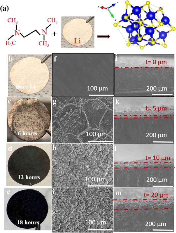
a Schematic for response of TEMED with Li0 to supply lithium nitride. b–e Photographic photos of naked Li0 and TEMED-treated Li0 for various remedy instances. f–i The corresponding cross-sectional SEM photos of naked Li0 and TEMED-treated Li0. j–m The corresponding top-view SEM photos of naked Li0 and TEMED-treated Li0.
Materials characterization, electrochemical spectroscopy, and transference quantity
Contact angle measurements have been carried out to find out the wettability of the electrolyte on untreated Li0 and TEMED-treated Li0 (Fig. 2a, b). To make sure good Li+ ion conductivity, fee functionality, and formation of a secure SEI, the electrolyte should be capable to considerably moist the electrode44. The contact angle for untreated Li0 is 41° suggesting poor wettability with the electrolyte which might trigger decrease ionic conductivity. In distinction, TEMED-treated Li0 exhibits a considerably decrease contact angle of 12° with electrolyte, suggesting that the TEMED-originated SEI is healthier interfaced with the electrolyte, which is helpful to homogenize ion distributions within the neighborhood of the adverse electrode, not solely supporting environment friendly Li+ transport but in addition prevents the undesirable morphologies (dendritic or useless Li0) which might be identified to be induced by uneven Li+ flux distribution45. The section purity of TEMED-treated Li0 was characterised by X-ray diffraction (XRD) (Fig. 2c). Distinct Li0 peaks of (110), (200), and (211) have been noticed at 36°, 52°, and 65°10 and Li3N peaks of (001) and (002) at 22.96° and 46.6°, respectively. The formation of hexagonal α-phase single crystal Li3N from TEMED-treated Li was additionally indicated by the transmission electron microscope (TEM) characterization as proven within the Supplementary Fig. 1. As compared, typical strategies to acquire Li3N, the place Li0 was handled with nitrogen movement present a polycrystalline construction with (001), (100), (002), (110), and (102) peaks for Li3N (Supplementary Fig. 2). XRD of Li3N after 100 cycles was additionally carried out to look at the change of section purity (Supplementary Fig. 3), revealing shocking structural stability of Li3N shaped by TEMED in opposition to cost/discharge biking, as evidenced by the sturdy α-phase peaks at 22.9° (001) and 46.6° (002). These α-phase Li3N diffraction peaks additionally reveal that the Li3N movie obtained from TEMED remedy is very oriented alongside the course vertical to the Li0surface, therefore provides glorious Li+ conductivity and implies a decrease Li+ migration power barrier46.
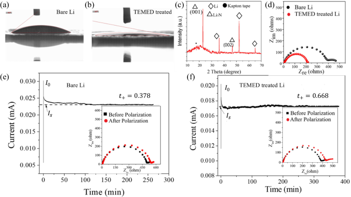
Contact angle measurements of a untreated Li0 and b TEMED-treated Li0. c XRD spectrum of TEMED-treated Li0. d EIS measurements of untreated Li0 and TEMED-treated Li0. Regular-state present beneath 10 mV polarization for e Li-Li symmetric cell f TEMED-Li/TEMED-Li symmetric cell. Inset exhibits EIS measurements earlier than and after polarization.
Electrochemical Impedance Spectroscopy (EIS) measurements have been carried out to additional characterize the electrode interface. Determine 2nd and Supplementary Fig. 4 evaluate EIS for untreated Li0 and for TEMED-treated Li0. The primary semicircle within the larger frequency vary signifies the interfacial resistance of the synthetic SEI or resistance of Li+ flux by means of a man-made SEI, whereas the second semicircle within the decrease frequency vary signifies the cost switch resistance Rct. The symmetrical cell constructed on untreated Li0 confirmed a excessive resistance of ~400 ohms, whereas for the TEMED-treated Li0 symmetric cell, we noticed a diminished resistance of ~200 ohms. We attribute the smaller general impedance of the TEMED-treated cell to the higher Li+ transport efficiency throughout the Li3N synthetic SEI shaped on the interface. The Li+ conductivity of the TEMED handled Li was calculated to be ~4.19 × 10⁻¹ mS cm−1 primarily based on the sequence resistance of the symmetric cell, a sufficiently excessive worth to determine a quick Li+ alternate channel between Li0 steel and electrolyte10.
The transference variety of Li+ on the interface between the Li0 electrode and the electrolyte was evaluated utilizing Bruce-Vincent Strategy. Excessive cation transference numbers are fascinating to keep away from focus gradients within the cell and to delay the nucleation and development of lithium steel dendrites whereas charging the cell at a excessive fee. It ought to be famous that in typical carbonate-based electrolytes, the transference quantity t+ is usually between 0.1 and 0.447. Though larger t+ might be obtained in polymeric, ceramic, or nanoparticle-based electrolytes, by which the anions are immobilized to a stationary or slow-moving assist, low ionic conductivity and different compromises in properties resembling interfacing or mechanical power at all times accompany them. We count on that the lithium nitride layer with a pure α-phase on high of Li0 will handle these conflicts. The transference numbers are decided in symmetric cells consisting of untreated Li-Li and handled Li-Li, respectively. The cell was initially conditioned to determine a secure interface by charging and discharging at 0.01 mA cm−2, with 4-h cost, 30-min relaxation, and 4-h discharge, with the method repeated 6 instances. The cell was then polarized at 10 mV for 10 h to make sure a gradual state (Fig. 2e, f). EIS spectra earlier than polarization and after the regular state had been reached are proven in inset of Fig. 2e, f. The steady-state cation transference quantity was then calculated by way of Eq. (1).
$${t}^{+}=frac{{I}_{s}(Delta V-{I}_{o}{R}_{o})}{{I}_{o}(Delta V-{I}_{s}{R}_{s})}$$
(1)
the place t+ is the steady-state cation transference quantity, (Delta V) is the utilized voltage, ({I}_{o}) is the preliminary present, ({I}_{S}) is the steady-state present, ({R}_{o}) is the preliminary interfacial resistance, ({R}_{S}) and is the steady-state interfacial resistance. The calculated outcome exhibits that the TEMED-treated Li electrode reveals a excessive steady-state cation transference variety of t+ = 0.668, untreated as compared with t+ = 0.37 for untreated Li0. This outcome strengthens our understanding that the TEMED-treated Li0/electrolyte interphase performs a dominant function in altering Li+ transport conduct. The advance within the cation transference quantity with the synthetic SEI layer has the potential to suppress dendrite development by decreasing the diffusion power barrier and regulating the ion focus on the interface in natural electrolyte relatively than solid-state electrolyte.
Section discipline simulation
The Arrhenius equation (Supplementary Word 3) signifies {that a} lower within the activation power results in a rise within the diffusion coefficient. This lower in activation power for diffusion lowers Li+ migration power obstacles which will increase ion transport on the interface between the electrode and electrolyte. The transference quantity is immediately proportional to its diffusion coefficient. Comparative Arrhenius-plots for TEMED-treated Li0, N2 handled Li0 and untreated Li0 are proven in Supplementary Fig. 5, revealing an activation power of 0.703 eV for untreated Li0, 0.613 eV for N2-treated Li0, and 0.48 eV. For TEMED-treated Li0, respectively. This successive lower in activation power ends in a a lot larger Li+ mobility, which in flip decreases the focus gradient throughout the corresponding SEI to supply a extra uniform floor for Li+ migration and plating. To check this speculation and to additional perceive the mechanism for suppression of dendritic and useless Li0 development by the Li3N-based SEI, we additional characterised the activation power of Li+ utilizing built-in section discipline simulations to elucidate the elemental correlation between our novel synthetic layer with section purity and the Li+ transport conduct on the interface, which we then confirm with the experimental outcomes. A extremely diffusive SEI is launched on the Li0 floor to imitate the handled Li0 lined beneath synthetic SEI. A small protrude is launched on the floor of the Li steel to imitate the nucleus of Li0. The diffusivity of Li+ within the electrode (({D}_{e})) and the electrolyte (({D}_{s})) are set to be 4.6 × 10⁻¹³ cm2/s and 4.6 × 10⁻¹⁰ cm2/s, respectively, whereas the diffusivity within the synthetic SEI layer (({D}_{i})) is 3 instances bigger than ({D}_{s}) for N2-treated Li0 and 10 instances for TEMED-treated Li0. These values are calculated primarily based on the activation power obtained from experiments (Supplementary Fig. 5). Determine 3a–c exhibits snapshots of the Li0 dendrite construction on untreated Li0, N2-treated Li0, and TEMED-treated Li0 having Li3N as a man-made SEI after 400 s, respectively. For untreated Li0, we observe that an preliminary Li0 protrude grows right into a filament-like dendritic morphology with facet branches budding from the first arm of the dendrite (Fig. 3a). For N2-treated Li0 adverse electrode, Li0 dendrite types and grows at a smaller development fee, and the facet development of the first arm of Li0 dendrite is hardly seen (Fig. 3b). As an alternative, the preliminary Li0 protrude types a dome-like morphology with a easy electrode-electrolyte interface, and its development fee is considerably diminished. It could possibly thus be inferred that the synthetic SEI layer of upper Li+ diffusivity and better Li+ transference quantity can certainly considerably suppress the dendritic Li0 development. To additional elucidate our findings, we plotted the 1D evolutions of Li+ focus alongside the x course throughout the tip of the dendrite, as indicated by the arrows within the 2D inset plots (Fig. 3c, d). The Li+ focus on the tip of the dendrite will increase sharply for untreated Li0 floor, whereas it will increase relatively step by step for handled Li0.
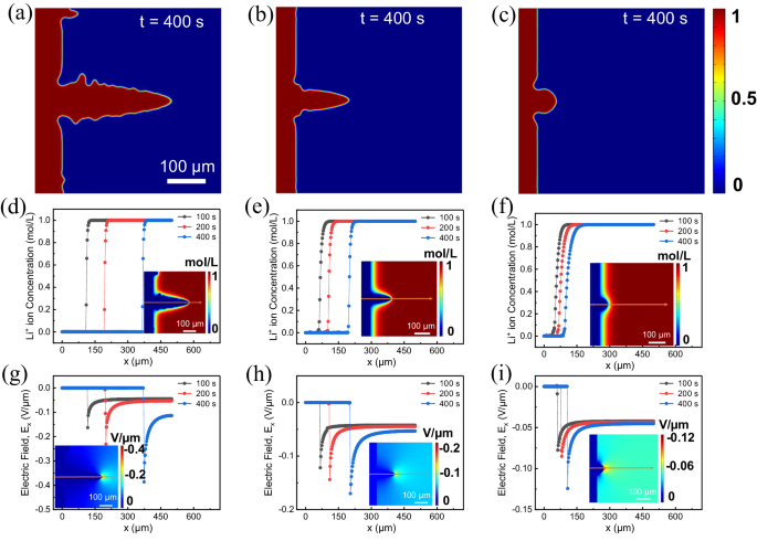
Dendrite morphology grown on a untreated lithium steel, b N2 handled Li adverse electrode, and c TEMED handled Li0 adverse electrode represented by phase-field variable ξ. d–f 1D evolutions of Li+ focus profile alongside x-axis throughout the tip of the dendrite for d untreated Li0, e N2 handled Li0, and f TEMED-treated Li0. The photographs on the inset present the 2D map of the Li+ focus at t = 400 s. g–i 1D evolutions of electrical discipline profile alongside x-axis throughout the tip of dendrite for g untreated lithium, h N2-treated Li0, and that i TEMED-treated Li0. The photographs on the inset present the 2D distribution of the native electrical discipline at t = 400 s.
The electrical discipline variation (({E}_{x})) alongside the dendrite tip at completely different time steps for untreated Li0, N2-treated, and TEMED-treated Li0 are additionally in contrast in Fig. 3g, i. The native electrical discipline stays virtually fixed within the electrode and electrolyte, however it’s maximized on the tip of the dendrite for all of the instances. Nonetheless, for untreated Li0 (Fig. 3g), the utmost ({E}_{x}) is 2 instances larger for that of the N2-treated Li0 and three instances for TEMED-treated Li0 (Fig. 3h, i), which is as a result of sharper tip morphology with bigger curvature, resulting in a better Li+ focus gradient close to the tip as a result of larger native electrical discipline that additional facilitates the expansion of the dendrite on an untreated Li0 floor. These outcomes point out that Li0 dendrite development is a self-accelerating course of, agreeing with earlier reports48. We additionally observe that for the untreated Li0(,{E}_{x}) on the dendrite tip and within the electrolyte resolution will increase to most over time. Whereas, for the handled Li0 adverse electrode, the variation in ({E}_{x}) at completely different time steps is way much less important, indicating that Li0 dendrite development is considerably inhibited.
Elemental evaluation, topography, and modulus mapping
X-ray photoelectron spectroscopy (XPS) was carried out on each TEMED-treated and untreated Li0 to decipher the chemistry of the synthetic SEI as proven in Fig. 4. All of the high-resolution spectrums have been fitted by the Lorentzian when it comes to spin-orbit doublets. Determine 4b exhibits the high-resolution N 1s spectrum, with peaks at 398.3 eV assigned to Li3N, which is understood to be a great Li+ conductor. The absence of any N 1s peak for untreated Li0 (Fig. 4e) confirms that the presence of Li3N arises solely from the response between TEMED and Li0. The C 1s (Supplementary Fig. 6) confirms that there is no such thing as a presence of every other natural moieties, and the wonderful efficiency of the battery is solely by the presence of Li3N. Moreover, we additionally detected the presence of N from the power dispersive spectrum (EDS), which exhibits the distinct presence of N and a uniform distribution of N over the floor of the TEMED-treated Li0 (Supplementary Fig. 7). Primarily based on the above evaluation derived from diversified strategies, we imagine that this N-rich SEI stabilizes the Li0/electrolyte interface, resulting in uniform Li0 electroplating and elevated cycle life.
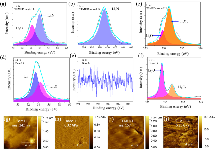
a Li 1s, b N 1s, and c O 1s XPS spectra of TEMED-treated Li0. d Li 1s, e N 1s, and f O 1s XPS spectra of untreated Li0. g AFM topography and h Younger’s modulus mapping of untreated Li0. i AFM topography and j Younger’s modulus mapping of TEMED-treated Li0.
Atomic power microscopy (AFM) was employed to visualise floor topography and measure the corresponding Younger’s modulus of untreated and TEMED-treated Li0 (Fig. 4g–j). The floor roughness values of the untreated and TEMED-treated Li0 have been in contrast by measuring the common floor root imply sq. (RMS) by way of high-resolution AFM, which for untreated Li (Fig. 4g) and TEMED-treated Li0 (Fig. 4i) are 242 and 157 nm, respectively. The upper RMS worth for untreated Li0 implies uneven and tough surfaces that may induce excessive native present on the protuberances and encourage Li0 dendrite on electrode surface49,50. In distinction, the sleek floor of TEMED-treated Li0 gives a route for uniform Li0 plating. The corresponding Younger’s modulus mapping values of untreated (Fig. 4h) and TEMED-treated Li (Fig. 4j) exhibit a median Younger’s modulus values of 0.32 and 6.85 GPa, respectively. We attribute the 20 instances larger Younger’s modulus worth of TEMED-treated Li0 to the superior structural effectivity and powerful mechanical power of the extremely oriented α-phase Li3N. This Younger’s modulus worth is considerably larger than the brink worth of 6.0 GPa for Li0 development, indicating that the TEMED-originated SEI is mechanically sturdy to suppress the dendritic Li0 upon its crystallization11.
Electrochemical efficiency of TEMED-treated Li
To judge the electrochemical efficiency of the TEMED-based lithiophilic interphase, symmetric cells with pristine and TEMED-treated Li0 have been cycled at varied present densities (0.5 and 1 mA cm−2) with the platting/stripping capability of 1 mAh cm−2 in an electrolyte consisting of 1.0 M LiTFSI in 1,3-dioxolane/1,2-dimethoxyethane (DOL:DME = 1:1 by vol). Voltage profile versus biking time, and voltage hysteresis (estimated by calculating the common distinction between the voltage of Li stripping/plating) versus cycle quantity are proven in Fig. 5.
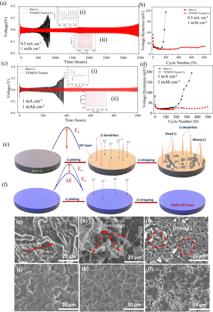
a, b Galvanostatic biking and voltage hysteresis at 0.5 mA cm−2/1 mAh cm−2. (insets present (i) quick circuit for untreated Li0, (ii) plating/stripping conduct of TEMED-treated Li0 at 1600–1640 h). c, d Galvanostatic biking and voltage hysteresis at 1 mA cm−2/1 mAh cm−2. (insets present (i) quick circuit for untreated Li0, (ii) plating/stripping conduct of TEMED-treated Li0 at 420–440 h). Schematic illustration of e Li0 dendrite development on untreated Li0 and f uniform deposition on TEMED-treated synthetic SEI. SEM photos of g–i untreated Li0, j–l TEMED-treated Li0 at fifth, twentieth, and one hundredth plating, respectively. The thickness of lithium chip is 450 μm. The size bars are at 20 µm.
The plating/stripping voltage profile of untreated and TEMED-treated Li0 was carried out to research the electrochemical stability of the TEMED-originated SEI. Determine 5a, c present the voltage profiles of plating/stripping for symmetrical cells constructed on untreated and TEMED-treated Li0 that achieved a capability of 1 mAh cm−2 on the present density of 0.5 and 1 mA cm−2, respectively. At a low present density of 0.5 mA cm−2, untreated Li0 exhibited massive voltage divergence after 150 cycles, and quick circuit after ~600 h. Nonetheless, TEMED-treated Li0-based symmetric cell confirmed a secure voltage profile with hysteresis under 20 mV, reflecting the secure plating and stripping course of for greater than 3500 h. Even at a better present density of 1 mA cm−2, TEMED-treated Li0 confirmed secure plating and stripping for greater than 500 cycles (1000 h), whereas untreated Li0 failed after ~400 h. TEMED-treated symmetric cells present secure efficiency even at a better present density of two mA cm−2 (Supplementary Figs. 8 and 9) and 5 mA cm−2 (Supplementary Figs. 10 and 11). 700 h and ~350 h have been achieved for two and 5 mA cm−2, respectively, for TEMED-treated Li0, in comparison with 150 and 50 h for untreated Li0. TEMED-treated Li0 additionally confirmed a secure plating and stripping cycle with business LiPF6-based electrolyte (Supplementary Figs. 12 and 13). The cell confirmed a secure plating and stripping for greater than 750 h on the present density of 1 mA cm−2 for TEMED-derived SEI whereas untreated Li0 failed after solely 270 h (Supplementary Figs. 14 and 15). The voltage hysteresis results in the identical conclusion for untreated Li0, a rise in voltage hysteresis was noticed with rising cycles in Fig. 5b, d. The overpotential will increase constantly, resulting in early failure of the cell after solely 200 cycles (~400 h). This huge hysteresis implies the formation of a extremely resistive and unstable interphase. The unstable SEI shaped throughout cell operation continues to devour electrolyte to restore new SEI, accompanied by the formation of dendritic and useless Li0, finally resulting in the early failure of the cell10. Symmetrical cell efficiency of the TEMED-treated Li0 at excessive present and excessive capability with 50-µm-thick Li0 have additionally been carried out to find out the compatibility of TEMED-originated SEI. 900 h and ~600 h have been achieved for the present density of 1 mA cm−2 and 5 mA cm−2 on the capability of three mAh cm−2, respectively (Supplementary Figs. 16 and 17), for TEMED-treated Li0, in comparison with 300 and 120 h for untreated Li0. Even on the excessive capability of three mAh cm−2 with 50-µm-thick Li0, TEMED-originated SEI ensures longer cycle life.
To raised perceive the morphology of Li deposition on untreated and TEMED-treated Li0, we carried out SEM examination after 5, 20, and 100 cycle. Determine 5e exhibits a schematic illustration of the expansion of dendritic and useless Li0 on the untreated Li0 after plating and stripping cycles, the place the native SEI from the response between Li0 and electrolytes are fragile, non-uniform, and unstable. Such SEI might be simply ruptured throughout electrode quantity modifications and by uneven plating/stripping.
In distinction, TEMED-treated Li0 (Fig. 5f) prevents facet reactions of Li0 with the electrolyte. Determine 5g–l exhibits the SEM photos of untreated Li and TEMED handled Li after fifth, twentieth, and one hundredth plating at 0.5 mA cm−2 with a capability of 1 mAh cm−2. For untreated Li0 we noticed uneven Li0 plating and dendrite development ranging from the fifth cycle (Fig. 5g). The unregulated and unprotected floor of the untreated Li0 creates massive protuberances producing a non-uniform electrical discipline. Dendrite development can also be promoted due to the uneven floor and domestically concentrated Li+ flux as a result of the sharp finish of those dendrites serves as a middle at which costs are inclined to accumulate10,51. This needle-like construction with a pointy finish might also penetrate by means of separator to trigger an inside quick circuit that ends in security issues52,53. As well as, the excessive floor space related to the dendritic morphology and facet reactions ends in a particularly low CE.
In distinction, the TEMED-treated Li0 results in a dense and nodule-like morphology within the absence of Li0 dendrites. Cross-sectional SEM (Supplementary Fig. 18) confirmed ~50 µm thickness Li0 after 100 cycles as in comparison with ~19 µm for the TEMED-treated Li0. Even after 100 cycles, the floor of TEMED-treated Li0 nonetheless maintained a compact floor with out discernible dendrites (Fig. 5l). Therefore, our structural characterization at a excessive stripping/plating fee over lengthy biking instances additional helps the speculation that top transference variety of Li+ throughout TEMED-originated SEI improves Li+ mobility, which in flip decreases the focus gradient, resulting in uniformity of Li0 electrodeposition with suppressed lithium dendrite formation.
Nucleation overpotential is outlined because the voltage distinction between the start voltage dip and the next flat plateau throughout plating, which is also called the Li nucleation barrier (Supplementary Fig. 19). Decrease nucleation overpotential signifies larger lithiophilicity and is most well-liked for larger reversibility of Li0 chemistry. Untreated Li0 exhibits a better nucleation overpotential of 37 mV indicating a considerably massive power barrier whereas, TEMED-treated Li0 exhibits larger lithiophilicity with the bottom nucleation overpotential of 15 mV. Electrochemical efficiency of L−2i0||Cu half cell and TEMED-Li0||Cu cell with the skinny Li0 chip of fifty µm thickness have been carried out on the biking present density of 1 mA cm−2 and capability of 1 and three mAh cm−2 (Supplementary Fig. 20 and 21, respectively). The CE of the untreated-Cu cell decreases quickly after solely 75 cycles; nevertheless, the CE of the TEMED-Li0||Cu cell maintains a secure cycle throughout 175 cycles for a capability 1 mAh cm at present density of 1 mA cm−2. The improved CE and lifespan have been additionally important when the capability was elevated to three.0 mAh cm−2 (Supplementary Fig. 20).
To judge the compatibility of TEMED-treated Li0 as a adverse electrode for sensible LMBs, we adopted lithium iron phosphate (LFP) and NMC-111 as two constructive electrode supplies to assemble a full cell LMB. Determine 6a exhibits the biking efficiency of the complete cell utilizing untreated or TEMED-treated Li0 because the adverse electrode at a continuing particular present of 160 mA g−1. We noticed linear degradation in capability for the complete cell with untreated Li0 because the adverse electrode (Fig. 6a). Nonetheless, with the TEMED-treated Li0, we obtained a gradual and secure capability for the complete cell. In fee functionality checks (Fig. 6b), at decrease particular currents of 32, 80, and 160 mA g−1 we noticed comparable capability for untreated and TEMED-treated Li0. Nonetheless, excessive particular currents of 800 to 80 mA g−1 result in a big capability loss for untreated Li (Supplementary Figs. 22 and 23). TEMED-treated Li0, alternatively, recovers virtually 100% of capability, as a result of secure dendrite-free Li0 plating/stripping of the TEMED-treated Li0. LFP-based full cell with a excessive mass loading (~9.5 mg cm−2) has additionally proven an improved efficiency for the TEMED-treated Li0 as in comparison with the untreated Li0. In the course of the tenth cycle Li0/LFP confirmed a discharge capability of ~135 mAh g−1 whereas TEMED-Li0/LFP confirmed a discharge capability ~123 mAh g−1 (Supplementary Fig. 24). After the fiftieth cycle (Supplementary Fig. 25) capability retention of ~74% has been obtained for TEMED-Li/LFP as compared with ~50% for untreated Li0/LFP full cell. Comparable efficiency has been obtained for NMC-based cells the place a drastic decline in capability for untreated Li/NMC with capability retention of ~48% has been obtained as in comparison with 73% for TEMED-Li/NMC after 200 cycles (Supplementary Figs. 26–28) suggesting that the synthetic SEI originated from TEMED is extra stabilized.
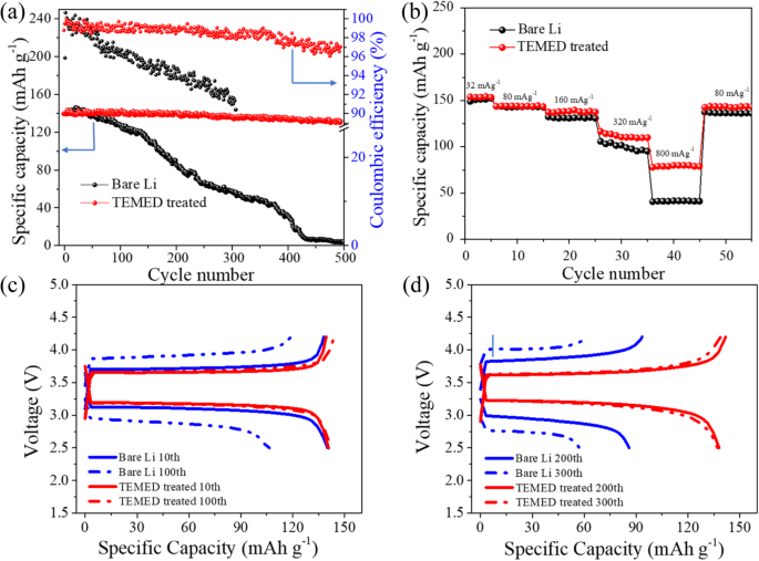
a Biking efficiency of full cells primarily based on LFP constructive electrode and untreated or TEMED-treated Li adverse electrode at a selected present of 160 mA g−1. b Charge performances of full cells primarily based on LFP constructive electrode and untreated or TEMED-treated Li adverse electrode. c, d Cost/discharge voltage profiles at completely different cycles of full cells primarily based on LFP constructive electrode and untreated or TEMED-treated Li adverse electrode at 160 mA g−1. The mass loading of LFP is ~2.0 mg cm−2.
Determine 6c, d exhibits the biking efficiency and voltage profile of full cells utilizing each untreated Li and TEMED-treated Li as a adverse electrode. Untreated Li0/LFP full cells confirmed a decrease CE within the first cycle, which may very well be attributed to Li0 consumption and electrolyte decomposition to type the SEI. TEMED-treated Li0 confirmed ~100% capability retention from the tenth discharge to the one hundredth discharge. In distinction, the tenth particular discharge capability of untreated Li/LFP full cell exhibits a pointy lower from ~140 to 102 mAh g−1, retaining 72.8% on the one hundredth cycle. With elevated cycle numbers, the lower in capability retention turns into extra distinguished for untreated Li/LFP. Diminished overpotentials have been additionally noticed for the TEMED Li/LFP full cell whereas, naked Li/LFP exhibits larger overpotential as a result of lack of Li and consumption of electrolyte from facet reactions and an un-stabilized SEI with dendrites, resulting in overpotential and sluggish Li-ion transportation. The secure cycle life and low polarization potential recommend that the TEMED-treated Li adverse electrode is able to working beneath sensible biking circumstances.


