
Single-chamber experimental setup and SOFC anode activation
The cell structure investigated right here consists of an LSM/YSZ cathode, a YSZ electrolyte and a NiO/YSZ anode, as proven in Fig. 1. To make sure industrial relevance, the SOFC investigated right here was produced by SolydEra S.p.A. utilizing tape-casting. The electrolyte was made thinner (2 µm) than regular to allow the fabrication by FIB of a TEM lamella containing all of the related interfaces of the cathode-electrolyte-anode cell. The lamella was contacted to a MEMS chip from DENSsolutions with simultaneous heating and biasing capabilities (Fig. 1a, see Supplies and Strategies for particulars). The TEM lamella was mounted onto a prototype DENSsolutions MEMS holder and inserted within the column of a FEI Titan G2 environmental transmission electron microscope (ETEM). A scanning TEM (STEM) annular dark-field picture (ADF) picture of the as-prepared SOFC is proven in Fig. 1b. Corresponding elemental maps obtained by STEM power dispersive X-ray spectroscopy (EDX) are displayed in Fig. 1c, highlighting how the totally different phases are distributed within the preliminary pattern. The YSZ electrolyte is dense with grains of about 1–2 µm, whereas the LSM/YSZ cathode is porous to make sure oxygen entry to the TPBs (LSM-YSZ-porosity on the cathode facet). Alternatively, the NiO/YSZ anode precursor is dense in its as-sintered state.
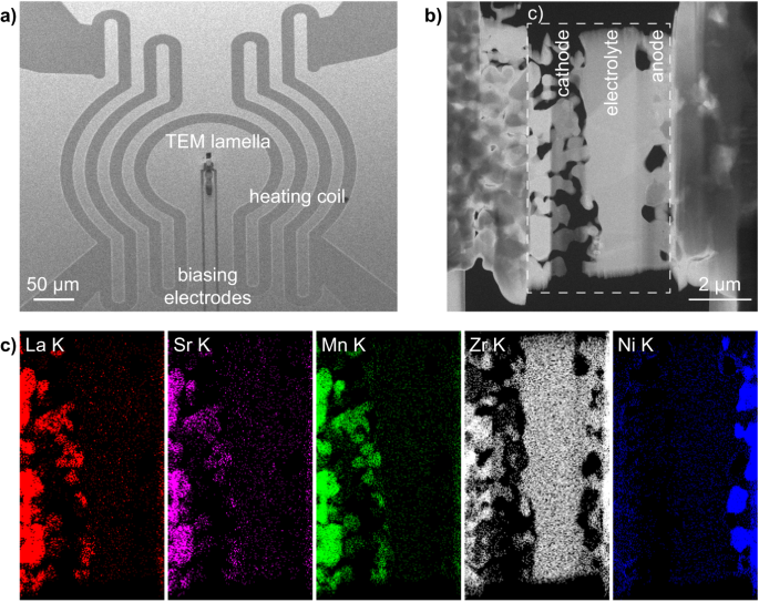
a Scanning electron microscopy (SEM) picture of a MEMS chip for operando transmission electron microscopy (TEM). The anode and cathode of the SOFC lamella are electrically linked to the biasing electrodes of the MEMS. b STEM ADF micrograph of the electrically linked SOFC pattern, and c corresponding STEM EDX maps of the Ok edges of the primary parts current within the preliminary SOFC gadget acquired from the dashed space proven in b.
Previous to operation, the as-sintered NiO section must be lowered to Ni, its energetic state. The porosity that may outcome from the method will even allow to kind TPBs on the anode side5. To activate the Ni catalyst of the cermet, 10 to fifteen mbar of forming fuel (5 v/v% of H2 in N2) was launched within the ETEM, a strain approaching the maximal strain allowed within the environmental chamber. The temperature was elevated as much as 750 °C to set off the discount of NiO to Ni. STEM ADF micrographs acquired at varied temperatures and pressures are given in Fig. S1, highlighting how the microstructural adjustments happen within the anode in the course of the activation of the Ni. The discount response turns into seen by the creation of pores throughout the NiO grains, with pores forming preferentially on the interfaces with YSZ as a result of a fast coarsening of the Ni section at these temperatures. As highlighted in prior studies39, 40,48,50, the NiO discount kinetics is sluggish contained in the ETEM in these circulation and strain circumstances. The response price is initially managed by the nucleation of the primary Ni seeds. The presence across the response websites of H2O launched by the discount then doubtless slows down the response price at excessive conversion fractions. Alternatively, the cathode stays unchanged in forming fuel as much as this temperature of 750 °C and inside this time scale of 210 minutes (Fig. S2).
H2-to-O2 fuel ratio, SOFC voltage and microstructure
To set off the operation of the SOFC lamella in a single-chamber configuration, the temperature was lowered to 600 °C. Along with limiting thermal stress, this temperature was chosen on this single-chamber configuration to restrict the exercise of the LSM cathode in the direction of the gasoline oxidation reaction59, whereas nonetheless making certain the exercise of the Ni/YSZ anode in the direction of this response (>550 °C)60. The forming fuel H2/N2 circulation was set to three ml/min earlier than introducing a further circulation of O2 of ~0.1 ml/min, resulting in an rising O2-to-H2 ratio within the ETEM. Observe that the O2 circulation was set to the minimal worth allowed by the Brooks mass circulation controller forward of the ETEM. In these circumstances, the whole strain within the ETEM chamber reached 15.8 mbar.
We investigated the affect of a various O2-to-H2 ratio and monitored the cell open circuit voltage (OCV) in relation to the morphology of the Ni catalyst (Fig. 2). Observe that a number of reduction-oxidation cycles passed off between Figs. S1 and a pair of. Determine 2a plots i) the evolution with time of the common TEM picture depth of the 2 Ni grains proven in Fig. 2b–g (i.e., depth of the picture averaged over the realm of the 2 grains), ii) the ratio between the O2 and H2 alerts obtained from the residual fuel analyser (RGA) appended to the exit of the ETEM chamber, and iii) the OCV between the 2 MEMS biasing electrodes (see Fig. 1a). The as-measured RGA O2-to-H2 ratio information (full line) was superior by 180 seconds to right for the time wanted by the fuel to journey from the response chamber to the RGA (dashed line, see Supplies and Strategies part for particulars). Determine 2b–g exhibits a choice of TEM photographs detailing the evolution of the 2 Ni grains, the intensities of that are plotted in Fig. 2a. The complete sequence of TEM photographs of Fig. 2 is out there on-line ( From Fig. 2a, a direct correlation between Ni grain common depth, presence of O2, and OCV between the anode and cathode is seen. When introducing O2 within the ETEM chamber, the picture depth stays fixed for about 500 s, which coincides with a small enhance in OCV between the MEMS electrodes. Because the O2-to-H2 ratio will increase additional (from 600 s to 1500 s), the OCV drops quickly again to a worth near its preliminary baseline, whereas the Ni grains change into darker. This reducing of the TEM picture depth is indicative of an oxidation of the Ni grains to NiO: oxygen is integrated within the Ni grains, resulting in a thickening of the grains and to the filling of voids (see arrowheads in Fig. 2b–d), which in flip decreases the variety of electrons collected by the TEM digicam as a result of further scattering to excessive angles. This oxidation of the Ni catalyst within the TEM photographs is confirmed by monitoring the evolution of electron energy-loss spectra (EELS) of the Ni-L2,3 edges (Fig. S3). The rising depth of the Ni-L3 edge (~855 eV) with respect to the L2 edge (~872 eV) signifies an oxidation of Ni in the course of the first a part of the experiment61. As mentioned elsewhere39,49,62, this quantity enlargement of Ni upon oxidation is bigger than that predicted by the Pilling-Bedworth ratio as a result of unbalanced mass transport mechanisms. On this temperature vary <1000 °C, Ni2+ ions diffuse outwards by the NiO scale grain boundaries quicker than O2- ions diffuse inwards, resulting in the injection of vacancies on the Ni/NiO interface and finally to the formation of inner voids throughout the rising NiO scale. When stopping the O2 circulation at ~1500 s, a delay of a number of minutes (till ~2300 s) is noticed earlier than the picture depth begins to extend once more because the NiO grains cut back again to Ni (Fig. 2f). The Ni grains shrink in the course of the discount response and porosity re-appears inside these grains (see arrowheads in Fig. 2e–g). In parallel, the OCV begins to extend when O2 is eliminated after ~1500 s, earlier than reducing from ~2500 s onwards. The OCV will increase and reduces at a slower price in comparison with the primary peak (when O2 was launched within the chamber).
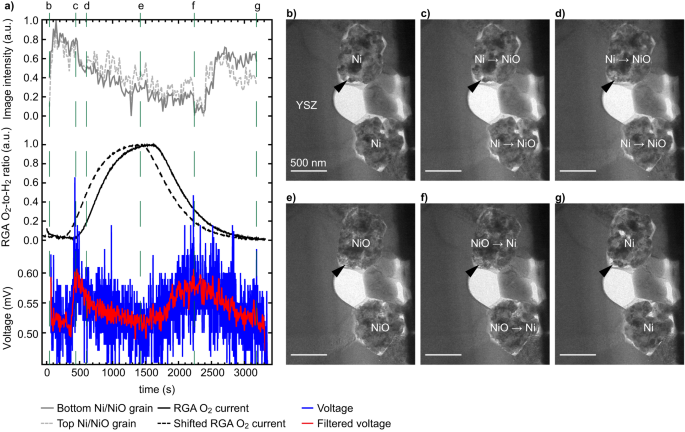
a Plots exhibiting the evolution with time of the common TEM picture depth measured on the location of two Ni grains, the ratio of the residual fuel analyser (RGA) O2 and H2 alerts (uncooked information, full line, and curve shifted ahead by 180 seconds, dashed line), and the voltage measured between the 2 biasing electrodes (uncooked information in blue and after the applying of a gaussian filter in pink, see supplementary info for particulars). b–g Choice of corresponding TEM photographs of the 2 Ni grains situated subsequent to the yttria-stabilised zirconia (YSZ) electrolyte, the depth of which is reported in a, taken at vital steps of the oxidation and discount processes. Arrowheads spotlight morphological adjustments occurring in the course of the oxidation after which discount of Ni, see textual content for particulars.
Correlation between Ni oxidation state and SOFC voltage
From Fig. 2c and the EELS information of Fig. S3, it seems that the primary enhance in OCV is correlated with the presence of Ni in its metallic state (smaller quantity, compact morphology with some open porosity as proven by the arrowhead, decrease Ni L3/L2 EELS ratio). To rationalise the OCV variations noticed in Fig. 2 and clarify the second OCV peak, related sequences capturing the oxidation and discount of the Ni catalyst have been carried out at greater spatial decision. Determine 3 particulars the morphological adjustments occurring on the floor of 1 Ni grain throughout an oxidation after which a discount. Determine 3a exhibits the evolution in time of an depth profile taken throughout a Ni/void interface, which is proven within the type of a contour plot (taken from the area marked by an arrow in Fig. 3b). The RGA and OCV information are additionally plotted in Fig. 3a. A primary enhance in OCV is noticed after ~380 s, which coincides with the presence of each O2 and H2 within the ETEM chamber and with Ni in its metallic state (as in Fig. 2). Certainly, the depth profile taken on the floor of 1 Ni grain doesn’t change throughout these early levels, regardless of the (low) O2 partial strain now being current within the chamber (Fig. 3a). The dense Ni grain morphology stays similar between Fig. 3b, c. Because the O2-to-H2 ratio will increase after 400 s of experiment, a NiO scale begins to kind on the metallic Ni grain (Fig. 3d). The floor of the Ni grain retracts in the direction of the centre of the Ni grain (see dashed line marking the Ni/NiO interface in Fig. 3a, d, e). The Ni grain is now lined by a NiO scale that expands outwards. The TEM picture depth throughout the area that was beforehand a void now decreases as NiO is now forming there (arrowhead in Fig. 3a, d). As soon as the O2 circulation is stopped and the O2-to-H2 ratio begins to lower after 1500 s, the place of the Ni/NiO interface stops retracting and stays motionless alongside the y axis of the road profile. In parallel, the depth on the location of the NiO scale begins to lower additional (see black arrow in Fig. 3a, e). As it will likely be confirmed beneath in Fig. 4, this loss in depth outcomes from the expansion of latest Ni domains straight on the NiO scale because the O2-to-H2 ratio decreases. The OCV will increase when Ni is current on the outer floor of the NiO scale. Moreover, Ni L3,2 EELS information proven in Fig. S3 is in line with such a combined NiO/Ni system: an intermediate L3/L2 ratio is measured in these circumstances. After 2200 s, the Ni/NiO interface is noticed to maneuver downwards because the NiO scale disappears and the Ni islands current on the dimensions floor merge with the centre of the Ni grain which didn’t totally cut back (see half black half white arrows in Fig. 3a, f). In Fig. 3g, the NiO scale has utterly disappeared. The second voltage enhance from ~1500 s to ~2300 s is broader than the primary one. The complete dataset used to make Fig. 3 is out there on-line (
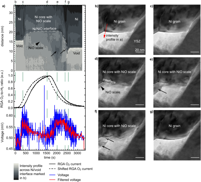
a Contour plot of the evolution of the TEM picture depth taken alongside the arrow proven in b, the residual fuel analyser (RGA) O2-to-H2 ratio (uncooked information, full line, and shifted ahead by 180 seconds, dashed line), and open circuit voltage measured between the anode and cathode (uncooked and gaussian-filtered information). b–g Choice of TEM photographs of the sting of a Ni grain on the vital steps of the reoxidation and discount processes. Black arrows and arrowheads spotlight key morphological adjustments occurring on the floor of the Ni grain, as mentioned within the textual content.
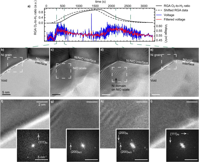
a Residual fuel analyser (RGA) O2-to-H2 ratio (uncooked information, full line, and shifted ahead in time by 180 seconds, dashed line), and open circuit voltage measured between the anode and cathode (uncooked and gaussian-filtered information). b–e Excessive-resolution TEM photographs of the sting of a Ni grain on the vital steps of the reoxidation and discount processes, and f–i Fourier-filtered magnified micrographs and corresponding FFTs taken from the dashed areas in b–e. The interface of the Ni grain, with a void or with the NiO scale, is marked by a dashed line in b–e.
To confirm that the second OCV enhance coincides with the nucleation of Ni islands on the NiO scale, greater magnification photographs of the interface analysed in Fig. 3a are reported in Fig. 4. Lattice fringes will be periodically resolved, enabling an indexation of the totally different phases relying on the environmental circumstances. At low O2-to-H2 ratios, quick Fourier transforms (FFT) reveal that the presence of Ni (111) reflections coincides with the primary OCV enhance noticed after ~400 s (Fig. 4a), in settlement with earlier interpretations. When reaching greater O2 partial pressures, new crystalline domains kind on the floor of the Ni grains 550 s after the beginning of the experiment. Lattice fringes with the identical lattice spacing (~4.7 nm−1) however with a unique orientation than the father or mother Ni grain will be resolved: these are attributed to NiO (200) planes (Fig. 4c, g). As well as, faint reflections that correspond to NiO (111) planes can be detected (4.1 nm−1). At this level, the OCV begins to drop, which is in line with an oxidation of Ni. The O2 circulation was then stopped earlier than reaching a full oxidation of the Ni grains. After an incubation time (from 1500 s to 2150 s), Ni (200) reflections (5.3 nm−1) begin to seem on the NiO scale (Fig. 4d, h). This remark confirms the presence of Ni islands on the NiO scale in these intermediate O2-to-H2 ratio circumstances, which coincide with a rise in OCV. The NiO scale then turns into totally lowered after 2600 s because the O2-to-H2 ratio decreases: the Ni islands current on the floor finally merge with the father or mother Ni grain and the OCV drops again to its baseline worth (Fig. 4e, i). Because it was not totally oxidised, the Ni grain retains its preliminary orientation after one partial oxidation and discount cycle. All the photographs of the experiment linked to Fig. 4 will be discovered on-line (
From Figs. 2–4, the rise in OCV of the single-chamber SOFC coincides with the presence of each metallic Ni on the outer floor of the anode and a small partial strain of O2 within the chamber. When certainly one of these two standards is just not fulfilled the OCV measured throughout the cell drops again to its baseline worth. It needs to be famous that the minimal circulation allowed by the mass circulation controllers coupled with the utmost strain achievable within the ETEM chamber restricted us to transient experiments: a continuing O2-to-H2 ratio sustaining the Ni lowered within the anode facet and ample O2 to have a continuing OCV couldn’t be reached within the ETEM. In different phrases, the skinny lamella oxidised rapidly upon O2 publicity. These oscillations triggered by the oxidation of the Ni anode have additionally been reported in literature when finding out bulk systems58. One other remark is that the baseline voltage worth of about 0.55 mV measured right here doesn’t depend upon the fuel ambiance: it’s related in H2/N2 and in O2-rich atmospheres.
Single-chamber operation of ordinary SOFCs
The identical cathode-electrolyte-anode cell was studied ex situ in a single-chamber configuration at 600 °C. The distinction is that these ex-situ measurements carried out in an oven concerned atmospheric pressures and 14-mm diameter button cells as a substitute of pressures of some mbar and µm3 lamellae as within the ETEM. The outcomes proven in Fig. S4a reveal developments which might be qualitatively much like these noticed in situ within the ETEM. Ranging from a Ni/YSZ anode in a H2 ambiance, a primary peak in OCV happens at intermediate O2-to-H2 ratios (0.5) shortly after including O2 within the chamber. The OCV then decreases at greater O2 partial pressures, doubtless on account of the oxidation of the Ni catalyst. After reducing the O2 circulation halfway by the experiment, one other OCV peak seems when again to intermediate O2-to-H2 ratios. Lastly, the OCV decreases sharply as O2 is totally faraway from the chamber. One key distinction with environmental transmission electron microscopy experiments is that the OCV measured ex situ reaches 0.8 V, a normal worth for (single-chamber) SOFCs58. Moreover, from the ex-situ assessments proven in Fig. S4 and as-expected, the OCV is most across the stoichiometric O2-to-H2 ratio of 0.5.
The OCV forming between the cathode and anode of a SOFC will depend on the distinction between the oxygen partial pressures on the cathode and anode, ({P}_{{O}_{2,{cathode}}}) and ({P}_{{O}_{2,{anode}}}), respectively. The OCV is outlined by the Nernst equation ({OCV}=frac{{RT}}{{nF}}{{{{mathrm{ln}}}}}(frac{{P}_{{O}_{2,{cathode}}}}{{P}_{{O}_{2,{anode}}}})), the place R is the perfect fuel fixed, T the temperature, n the variety of electrons concerned within the response, and F the Faraday constant58. In a single-chamber SOFC, this distinction in ({P}_{{O}_{2}}) outcomes from the distinction in selectivity between the electrodes: the anode must favour the partial oxidation of the gasoline (({{{rm{H}}}}_{2}+{{{rm{O}}}}^{(2-)} leftrightarrow {{{rm{H}}}}_{2} {{{rm{O}}}}+{{{rm{2e}}}}^{-}), reversible response at OCV), whereas the cathode ought to promote the electrochemical discount of the oxygen (({frac{1}{2}O}_{2}+{2e}^{-} leftrightarrow O^{2-}) at OCV). Primarily based on the Nernst equation, the small OCV positive aspects over the baseline measured within the ETEM of 0.1 mV correspond to a distinction in ({P}_{{O}_{2}}) between cathode and anode of 0.5%. Whereas this worth is orders of magnitude beneath the OCV measured ex situ (0.8 V), solely few TPBs are current within the skinny TEM lamella to create this distinction in ({P}_{{O}_{2}.}) Moreover, strain circumstances differ by a number of orders of magnitude when evaluating experiments carried out within the ETEM to those at atmospheric strain within the oven.
To guage whether or not this distinction in ({P}_{{O}_{2}}) between anode and cathode may additionally outcome from the total oxidation of the gasoline straight within the anode (({H}_{2}+{frac{1}{2}O}_{2}leftrightarrow {H}_{2}O)) with the cathode remaining inactive, we measured in an oven the OCV of an electrolyte-anode half-cell contacted utilizing a Au mesh as a perform of the O2-to-H2 ratio (Fig. S4b). The half-cell system reveals a unique behaviour than the total cell: a single enhance in OCV is noticed initially at rising O2-to-H2 ratios, adopted by a sluggish OCV decay because the O2-to-H2 ratio is saved fixed after which decreased again to 0. When ramping up the O2 circulation to achieve the stoichiometric O2-to-H2 ratio of 0.5, it seems that the primary peak in OCV happens regardless of the presence of the cathode. Alternatively, the second enhance in cell OCV beforehand noticed with full cells is just not measured with the half-cell system. The cell OCV turns into detrimental in the direction of the top of the experiment, indicating that the anode finally begins to behave as a cathode with respect to the Au electrode in these conditions63. Such detrimental voltages are sometimes noticed when NiO reduces to Ni (Fig. S5). As Au is inert in the direction of the fuel64, the absence of such detrimental OCV values in experiments carried out with full cells point out that the cathode is energetic and contributes to the general electrochemical response, at the least for the second OCV peak. It needs to be famous that the constrictivity and tortuosity of the totally different parts of the total cells or half button cells have an effect on the OCV developments measured ex situ (see Fig. S6 for cross-section SEM picture of the button cell). Certainly, the oxidation state of the Ni section will evolve in time all through the anode as a perform of the fuel ambiance, which can have an effect on the permeation of the totally different gases throughout the anode (because the Ni is oxidising/decreasing) and in flip the OCV (see Fig. S7 and related clarification). The impact is absent in environmental transmission electron microscopy experiments as a result of distinction within the geometry of the samples underneath take a look at (skinny lamellae with massive free surfaces versus bulk samples).
Single-chamber SOFC operation within the ETEM
Lastly, to judge additional the exercise of the cathode straight within the ETEM, the current-voltage traits of a full cathode-electrolyte-anode cell have been measured as perform of the fuel ambiance composition (Fig. S8). For these experiments, a skinny TEM lamella that includes the total cathode-electrolyte-anode cell was linked to a sourcemeter as a substitute of a voltmeter. The outcomes needs to be analysed with care as currents within the pA vary are measured. The electron beam was therefore blanked throughout these experiments to keep away from impacting the J-V information. Variations in O2-to-H2 ratio are discovered to have an effect on the general current-voltage developments. Beginning with Ni in its metallic state in a decreasing ambiance as in Figs. 2–4, the introduction of a small circulation of O2 within the ETEM chamber leads current-voltage traits qualitatively much like these measured with bulk SOFCs, with the skinny lamella delivering what seems to be a small energy in these circumstances. At longer O2 exposures, Ni totally oxidises to NiO and the system turns into extremely resistive and therefore unable to “generate” any energy. Mixed with the ex-situ analyses detailed above evaluating full and half cells, these current-voltage measurements obtained right here within the ETEM point out that the skinny lamella appears to be functioning contained in the microscope, which means that each the cathode and anode are energetic.
Determine 5 rationalises the operando observations obtained contained in the ETEM. Beginning with the Ni catalyst in its metallic electrochemically energetic state, the OCV stays low at small O2-to-H2 ratios because the O2 electrochemical discount response on the cathode facet is inhibited as a result of absence of O2 (Fig. 5a). At rising O2-to-H2 ratios, a small but measurable OCV acquire is measured (Fig. 5b). Whereas the total oxidation of the gasoline straight on the anode might contribute to this primary OCV acquire, the distinction in selectivity between the anode and cathode additionally ensures that a number of the O2 reduces on the cathode and a number of the H2 oxidises partially on the anode. Because the O2-to-H2 ratio continues to extend, the Ni catalyst begins to oxidise on its floor, which inhibits the adsorption and dissociation of H2, and therefore stops the electrochemical response (Fig. 5c). When the O2-to-H2 ratio decreases, Ni islands begin to nucleate on the NiO scale, resulting in the formation of electrochemically energetic websites within the anode and to a second OCV acquire (Fig. 5d). The NiO scale then utterly reduces to metallic Ni because the O2-to-H2 ratio decreases additional. Under a sure O2-to-H2 ratio threshold, the partial strain of O2 is inadequate to maintain the oxygen discount response within the cathode and the H2O formation response stops (Fig. 5e).
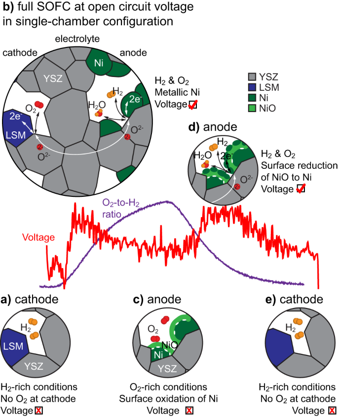
a At low O2-to-H2 ratios, the absence of O2 prevents its discount on the cathode. b When introducing O2, the cell begins to ship a voltage synonym of its operation till (c) the floor of the Ni grains oxidises. d When reducing the O2-to-H2 ratio, the floor of the NiO scale begins to scale back into Ni islands, re-initiating the oxidation of the gasoline on the anode, which ends up in a voltage enhance. e The method stops at low O2-to-H2 ratios (as in a). YSZ stands for yttria-stabilised zirconia, LSM for lanthanum strontium manganite.
Total, we demonstrated right here {that a} SOFC will be analysed operando in a single-chamber configuration by environmental transmission electron microscopy. Each H2 and O2 have been launched within the microscope chamber, while conserving the cell at excessive working temperature (600 °C) and observing its microstructure right down to the atomic scale. By various the O2-to-H2 ratio, direct correlations between cell OCV, fuel ambiance and microstructure of the Ni catalyst have been established. At intermediate O2-to-H2 ratios and when the Ni catalyst is maintained in its metallic state, a small but distinct acquire in OCV between the 2 electrodes of the skinny FIB-prepared lamella is measured. Primarily based on the comparability with ex-situ experiments and current-voltage measurements obtained in situ within the microscope, the OCV that builds up in these circumstances seems to outcome at the least partially from the distinction in selectivity between the anode and cathode for the partial gasoline oxidation and oxidant fuel discount reactions, respectively. Relying on O2-to-H2 ratio, the floor oxidation of Ni stops the gasoline oxidation response, whereas the expansion of Ni islands on the NiO scale restarts it. Wanting forward, such operando experiments within the ETEM ought to allow to research a variety of degradation pathways affecting SOFCs/SOECs, notably the poisoning of electrochemically energetic TPBs of each cathode and anode, or the affect of a coarsening of the Ni catalyst.


