
Extraordinarily lean electrolytic testing methodology
Determine 1a depicts the mechanism of inhibiting electrolyte decomposition by means of the implementation of an electrolyte-blocking layer on the floor of lively supplies. A considerable portion of electrolyte molecules on the unstable floor of lively supplies is inclined to electrochemical decomposition, resulting in the consumption of Li ions within the type of a SEI layer. Nevertheless, when the floor is passivated with a selective Li-ion conducting layer, the probability of solvent molecules reacting with the floor decreases. Consequently, this strategy alleviates the consumption of Li ions from the electrolyte, thereby enabling the cell to maintain a secure capability. Subsequently, the deterioration in capability could be quantified based mostly on the response kinetics of electrolyte decomposition43. Using a derived kinetics mannequin, a three-dimensional (3D) contour plot representing cell capability could be constructed. This plot integrates key variables from established kinetics, together with time, charge fixed (Rf,0), and a quantitative indicator of SEI development denoted as D (δ/L0), the place δ and L0 are constants proportional to the molar quantity and preliminary thickness of the SEI layer, respectively (Fig. 1b and Supplementary Be aware 1). Right here, the speed fixed and quantitative indicator for SEI development are material-specific, permitting for the conversion of capability degradation into phrases particular to the lively materials. In instances the place the electrolyte can not present extra Li ions throughout biking, the cell capability will decline quickly in accordance with the contour plot. To find out the precise depletion level of Li ions attributable to electrolyte decomposition inside the cell, it’s important to outline the circumstances beneath a particularly lean electrolyte employment (Fig. 1c). As soon as the provision of electrolytic species inside the cells is depleted to a stage inadequate for cell operation, the dominance of cell failure ensues, leading to a capacitive plunge within the cell capability. Subsequently, by monitoring and evaluating the cycles at which the capacitive plunge happens beneath particular cell configurations, a rational mannequin for evaluating the cell efficiency of assorted lively supplies and battery programs could be established.
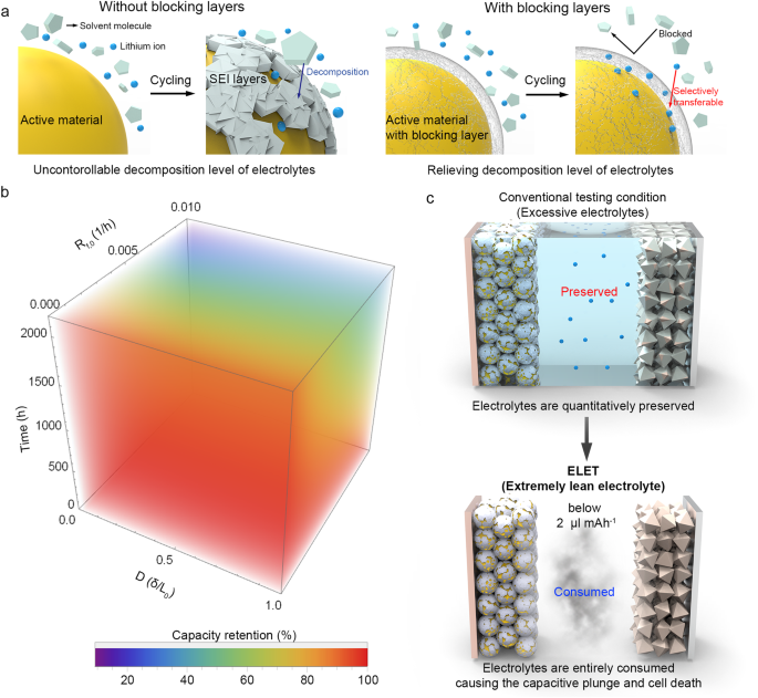
a Schematic depicting the mechanism of the inhibition of SEI layer development by means of the introduction of the electrolyte-blocking layer coating. b 3D contour plot representing capability retention based mostly on a mannequin derived from the kinetics of SEI formation reactions. c Schematic illustrating the remark of electrolyte depletion utilizing the ELET method for assessing battery cycle life.
Characterization of the as-prepared lively supplies
When evaluating the diploma of electrolyte decomposition in LIB programs, it’s pertinent to make use of generally used business supplies. Si-C composites are extensively investigated and employed as anode supplies in sensible LIB purposes, regardless of their susceptibility to electrolyte decomposition owing to extreme quantity enlargement throughout battery operation. On this examine, we applied a blocking layer of PD fashioned by means of oxidative polymerization on the floor of Si-C composites to mitigate electrolyte decomposition (denoted as Si–C/PD, Supplementary Fig. 1)44. Following the coating of PD layers onto the Si-C composites, the presence of those layers was examined utilizing varied analytical strategies, together with X-ray diffraction (XRD) patterns and imaging analyses performed by means of transmission electron microscopy (TEM) and scanning electron microscopy (SEM) (Fig. 2a, 2b and Supplementary Figs. 2–4). Moreover, power -dispersive spectroscopic (EDS) elemental maps (Fig. 2c–2f) demonstrated the buildup of PD layers on the Si-C composite floor after 16 h of polymerization. This course of efficiently overcame the intrinsic hydrophobic nature of naked Si-C composite floor (Supplementary Fig. 5).

a TEM and b high-angle annular dark-field photos of the Si–C/PD-16 h pattern. c Overlayed EDS map of (b) with the indicators for d Si, e C, and f N. g XPS spectra of the Si–C/PD-16 h pattern with the C 1s and N 1s core–stage areas. C–C, C–N, and C=O bonds are listed as inexperienced, orange, and blue, respectively. h TGA curves of the samples produced after 0 h (black line), 1 h (inexperienced line), 2 h (orange line), 4 h (blue line), 8 h (brown line), and 16 h (grey line) of PD coating. i FT-IR spectra of the naked Si–C (black line) and Si–C/PD–16 h composites (orange line).
To deal with the difficulty of a discount in electrical resistance that may come up from the thick PD layer, the coating time for the PD layer was optimized by means of electrochemical impedance spectroscopy (EIS, Supplementary Fig. 6). Notably, the electrochemical impedance decreased when the coating time was restricted to 4 h, whereas impedance exhibited a pointy enhance past this length. This phenomenon could be attributed to the flocculation of Li ions inside the PD layer on the Si-C composite floor, thereby enhancing ionic mobility and exercise to floor reactions (Supplementary Fig. 7). Consequently, samples subjected to 2 and 4 h of coating time have been designated as Si-C/PD1 and Si-C/PD2, respectively. X-ray photoelectron spectroscopy (XPS) evaluation of the samples (Fig. 2g and Supplementary Fig. 8) unveiled a particular sign at 400.2 eV within the N 1 s core-level area of the PD-coated composites, confirming the formation of amide bonds inside the PD layer on the Si-C composite floor. Thermogravimetric evaluation (TGA) was employed to quantitatively assess the extent of PD coating on the Si-C composite (Fig. 2h). The Si-C composite coated with PD, generated after 16 h of oxidative polymerization, exhibited a weight lack of as much as 9 wt%, whereas Si-C/PD1 and Si-C/PD2 samples contained 2.7 and 4.0 wt% of PD layers (as summarized in Supplementary Desk 1). Moreover, the chemical construction of the PD blocking layer was investigated utilizing Fourier remodel infrared (FT-IR) spectroscopy (Fig. 2i and Supplementary Fig. 9). The noticed peaks at 1354, 1608, and 1514 cm–1 could be attributed to distinct options of PD, particularly the C-N-C bonds inside the indole rings, C = C bonds, and cyclized C = N bonds of PD, respectively. These outcomes present conclusive proof of the profitable utility of the PD layer onto the carbonaceous floor of the Si-C composite.
Cell efficiency checks utilizing the ELET methodology and the interpretation of ensuing commonplace contour plots
PD moieties have been successfully utilized as a passivation layer on the floor of Si-C composites, anticipated to help within the desolvation strategy of solvent molecules accompanying Li ions. To evaluate the impression of PD layers on electrolyte decomposition, significantly beneath lab-scale circumstances with an considerable provide of electrolyte, commonplace half-cell checks have been carried out on Si–C/PD, using ample quantities of electrolyte. Following 2 h of PD coating (Si-C/PD1), cyclic voltammetry (CV) evaluation revealed distinct cathodic/anodic peaks related to the lithiation modes of Si and C (Supplementary Fig. 10). Subsequently, cycle efficiency checks have been performed on naked and PD-coated composites produced after various coating durations (Supplementary Fig. 11 and Supplementary Desk 2). The pattern generated after 4 h of PD coating (Si-C/PD2) exhibited a barely enhanced biking stability when in comparison with different samples with thicker PD layer coatings. The voltage profile of the Si-C/PD2 pattern indicated minimal will increase in overpotentials after biking (Supplementary Fig. 12). However, it stays unsure whether or not the precise biking stability of the Si-C, Si-C/PD1, and Si-C/PD2 samples can successfully distinguish the efficiency of every cell in half-cell checks. In assessments of cell efficiency with extreme electrolytes, quantifying the lack of lively Li ions poses challenges as a result of capability degradation outcomes from a mix of fabric electrical resistance deterioration and Li ion loss as a result of SEI formation. Moreover, the introduction of additional Li ions from surplus electrolytes complicates the comparability of Coulombic effectivity and capability retention of cells, alongside these offered by the cathode. Subsequently, for exact cell efficiency analysis and standardization, it’s crucial to precisely assess the consumption of lively Li ions offered by the cathode through electrolyte decomposition whereas minimizing the affect of exterior Li sources. That is achieved by means of the implementation of the ELET situation.
Earlier than continuing with the ELET analysis, regular full-cell checks have been carried out utilizing the identical electrode configurations, but with a surplus of electrolyte (Fig. 3a, 3b). The preliminary capacities of the examined cells have been discovered to be 6.44, 6.42, and 6.43 mAh for the naked Si-C, Si-C/PD1, and Si-C/PD2, respectively, with the corresponding preliminary Coulombic efficiencies calculated at 83.8%, 83.9%, and 84.8%. It was noticed that the electrolyte decomposition tendency barely diminished with a rise within the thickness of the PD layer, attributed to the impact of PD layer in facilitating desolvation of the electrolytic species. Upon reaching 300 cycles, the capability retentions for the naked Si-C, Si-C/PD1, and Si-C/PD2 have been 59.3%, 62.0%, and 72.5%, respectively, comparable to capability retention enhancements of two.7% and 13.2% for Si-C/PD1 and Si-C/PD2 compared to the naked Si-C. Nevertheless, these outcomes don’t conclusively show a big distinction in capability retention between the Si–C/PD samples and the naked Si–C, resulting in an ambiguous evaluation of the cycle life enchancment. Furthermore, the extreme employment of electrolytes within the take a look at obscured the detection of capability plunging level over the cycles, difficult an correct, clear, and quantitative analysis of the cycle lifetime of cells. Nevertheless, the introduction of the ELET situation to cells presents the chance to systematically examine the connection between Li ion loss and electrolyte depletion, facilitating the institution of a standardized mathematical framework for evaluating cell cycle life. Within the implementation of the ELET method, coin cells have been assembled utilizing an exceedingly restricted quantity of electrolyte, which may very well be readily depleted.
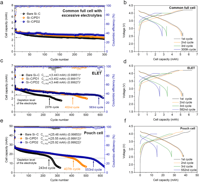
a Cycle efficiency of the naked Si–C, Si–C/PD1, and Si–C/PD2 composites by means of standard coin full cell checks. b Voltage profiles of the Si–C/PD2 pattern obtained by means of the coin full cell take a look at. c Cycle efficiency and capacitive plunging factors of the naked Si–C, Si–C/PD1, and Si–C/PD2 composites. d Voltage profiles of the Si–C/PD2 pattern decided by means of the ELET method utilizing a lean electrolyte (1.875 μl mAh–1). e Cycle efficiency and capacitive plunging factors of the naked Si–C, Si–C/PD1, and Si–C/PD2 composites. f Voltage profiles of the Si–C/PD2 pattern decided utilizing pouch cells with a lean electrolyte (1.875 μl mAh–1). For the cycle efficiency knowledge, black, orange, and blue circles are designated to the naked Si–C, Si–C/PD1, and Si–C/PD2 samples. For voltage profiles, black, orange, inexperienced, and blue traces correspond to the first, 2nd, third, and plunging (final) cycles.
These cells have been subsequently subjected to mathematical modeling for complete evaluation (Supplementary Figs. 13–16 and Supplementary Desk 3). Notably, the variations in stability curve slopes and reversible capability (Crev) values obtained by means of the ELET methodology have been extra pronounced (Fig. 3c and Supplementary Be aware 2). Furthermore, the prevalence of capacitive plunging factors ensuing from electrolyte depletion was conspicuously evident following ELET testing. Particularly, the plunging factors for every pattern have been noticed on the 237th cycle (naked Si-C), 402nd cycle (Si-C/PD1), and 583rd cycle (Si-C/PD2). It’s noteworthy that the PD-based blocking layers coated on the Si-C composite contributed to at the very least a 40% discount in electrolyte decomposition. Notably, the naked Si-C pattern examined with the ELET confirmed a decrease capability retention (64.2%) in comparison with the conventional full cell take a look at (65.8%). This means that a particularly lean electrolyte setting is inclined to electrolyte decomposition as a result of lowered interfacial contact between the electrolyte and electrode supplies, the place the electrolyte barely suffices to fill the pores inside electrode. In distinction, throughout regular full cell checks with extreme electrolyte, there isn’t a danger of electrode pores drying out as a result of electrolyte depletion. This situation inadvertently introduces extra electrolyte sources into the cell operation, accordingly resulting in an overestimated cycle life.
Moreover, throughout the voltage leisure area between the third and 582nd charging cycles, the place trapped Li ions are evenly redistributed, no substantial overpotential variations have been noticed (Fig. 3d and Supplementary Fig. 17). Contemplating the marginal enhance within the voltage on the finish of the discharging profile, the comfort step following galvanostatic discharge doubtless facilitated the uniform distribution of trapped Li ions all through the cell system, permitting for full retrieval of Li ions45,46. Subsequently, with the identical cell configuration, encompassing E/C and N/P (the capability ratio of damaging electrode to optimistic electrode) ratios, the cell efficiency of the ready samples was evaluated inside a pouch cell system that carefully emulated the ELET circumstances. As a result of the lean electrolyte situation is determined by the traits of separators and electrodes, a number of components attributed to the distinction of cell housing programs must be thought of with a view to emulate the cell efficiency from different housing programs. This pouch cell system yielded considerably larger capability in comparison with coin cells (Figs. 3e and 3f). Consequently, regardless of disparities in cell capability, the plunging cycle and the slope of capability fading exhibited notable similarity, implying that cell efficiency beneath the ELET situation can successfully mirror that of large-scale cell programs, thereby facilitating standardized efficiency analysis.
The ELET methodology is especially adept at maximizing the insertion and retrieval of Li ions from the electrolyte throughout cost and discharge cycles. This functionality permits for the formulation of a mathematical expression that captures the development of cycle efficiency of battery cells based mostly on the belief that Li ions irreversibly consumed throughout biking are completely utilized to generate the byproducts ensuing from electrolyte decomposition. The capability of a cell at a given cycle (Cn) throughout ELET testing could be mathematically expressed as a operate of the reversible capability (Crev), cell electrolytic effectivity (ε), and the cycle quantity (n), as proven in Eq. (1) (as additional detailed in Supplementary Be aware 2).
$${C}_{n}={C}_{{rev}}cdot {varepsilon }^{n}$$
(1)
Particularly, ε is the time period derived kinetically from the speed fixed for the electrolyte decomposition, time, and development stage of the SEI layer. It signifies the electrolytic effectivity inside the context of the ELET situation (Supplementary Be aware 2). When all the electrodes are constructed with ample cost/discharge effectivity, the capability fading primarily arises from the electrolyte decomposition, which is accompanied by an equal stage of Li ion consumption. Accordingly, ε can successfully seize the response kinetics associated to the formation of SEI layers (or electrolyte decomposition) with related variables, together with the speed fixed for the electrolyte decomposition, time, and development stage of the SEI layer, thereby serving as an indicator of electrolytic effectivity.
Moreover, gradual degradation of lively supplies, attributable to the interfacial delamination of those supplies (e.g. because of the volumetric enlargement of Si), adhesion failure, and structural modifications, is an important consider capability fading and electrical isolation over cycles of cells. This degradation happens progressively all through repeated cell operation, imposing limitations on the retaining of Coulombic effectivity throughout cycles47,48. Consequently, this results in a constant development in each capability fading and a lower in Coulombic effectivity, somewhat than abrupt modifications in efficiency. Nevertheless, it’s important to tell apart this from the abrupt capacitive degradation mode of capability plunging, which deviates from the continued capability development. Subsequently, a sudden drop in Coulombic efficiencies is extra appropriately attributed to emergent points throughout cell operation, such because the depletion of electrolytes. Mainly, our ELET strategy accounts for 3 main facets: capability, Coulombic effectivity (transformed into electrolyte effectivity), and the plunging prevalence in cycle efficiency. The components influencing capability tendencies are consequently mirrored within the noticed capability and Coulombic effectivity of the cells. For example, if a particular fraction of electrode supplies is steadily depleted over cycles, that is manifested as decreases in each capability and Coulombic effectivity. Since ELET efficiency assessments are based mostly on precise cell operation outcomes, it may be inferred that the ELET analysis inherently considers varied components impacting the capability development of cells.
To guage cell efficiency earlier than reaching the capacitive plunging level, it’s doable to calculate the full cell capability required to decompose 1 μl of the electrolyte (ctotal with a unit of mAh μl–1) utilizing Eq. (2) (as additional defined in Supplementary Be aware 3)
$${c}_{{complete}}=frac{{C}_{{rev}}}{{V}_{{electrolyte}}},left(frac{1-{varepsilon }^{{n}_{p}+1}}{1-varepsilon }proper),left(mathop{sum }limits_{n=1}^{3}{C}_{n,exp }ll {C}_{{complete}}proper)$$
(2)
the place Velectrolyte represents the amount of the electrolyte launched into the cell for ELET, np is the plunging cycle and Cn,exp denotes the experimental cell capability at a particular cycle. Consequently, when ctotal is represented as a 3D contour plot utilizing Eq. (2), it generates an analysis map displaying ctotal values (Fig. 4a).
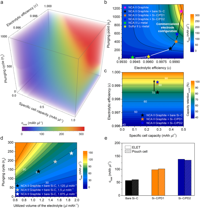
a 3D contour map illustrating cell efficiency as a operate of particular capability, plunging cycle (n), and electrolytic effectivity (ε). b 2D contour plot of ctotal contemplating ε and np. Pink, blue, orange, black, yellow, and inexperienced stars are designated to NCA–graphite, NCA–graphite/Si–C/PD2, NCA–graphite/Si–C/PD1, NCA–graphite/naked Si–C, sulfur–Li, and NCA–Li cells. c 2D contour plot depicting capability retention at 235th cycle in relation to the precise cell capability (Crev) and ε, the place black, orange, and blue stars are designated NCA–graphite/naked Si–C, NCA–graphite/Si–C/PD1, and NCA–graphite/Si–C/PD2 cells. d ELET outcomes with various electrolyte contents, the place black, grey, and white stars are designated to the cells with E/C ratios of 1.25, 1.5, and 1.875 μl mAh–1, respectively. e Comparability of ctotal values obtained from ELET and pouch cell checks. Naked Si-C, Si–C/PD1, and Si–C/PD2 samples are listed as black, orange, and blue colours, respectively. ctotal values obtained from ELET and pouch cell efficiency are listed as plain and dashed patterns, respectively.
For example, plotting ctotal as a operate of Velectrolyte and ε permits the capability tendencies of the cells to align with these of economic cell programs based mostly on the amount of electrolyte employed. Moreover, ε capabilities as a singular attribute of lively supplies, decided by the extent of electrolyte decomposition reactions induced by these supplies. This attribute facilitates standardized efficiency comparisons throughout varied materials varieties and battery programs. By deciding on appropriate values for Crev and Velectrolyte inside the ELET method, a two-dimensional (2D) contour map of ctotal, as a operate of electrolytic effectivity and plunging cycle, could be constructed utilizing Eq. (2) (Fig. 4b and Supplementary Fig. 18). The electrolytic effectivity of the naked Si-C composite was decided to be 0.99851, with its capacitive plunging level occurring after the 237th cycle. Based mostly on these values, the ctotal of the naked composite was decided to be 57.6 mAh μl–1. Conversely, following the implementation of PD layer coatings, the electrolytic efficiencies for the Si–C/PD1 and Si–C/PD2 samples elevated to 0.99917 and 0.99927, respectively. Correspondingly, the plunging factors have been considerably prolonged to the 402nd and 583rd cycles for these samples, respectively. Consequently, the ctotal values of the Si–C/PD1 and Si–C/PD2 samples markedly elevated to 98.6 and 138.6 mAh μl–1, respectively. This proves the importance of using electrolyte-blocking layer coatings on lively supplies as an efficient means to mitigate electrolyte decomposition.
The ELET methodology was primarily developed based mostly on the electrolyte depletion habits noticed throughout cell biking, which is a phenomenon that equally impacts most post-secondary batteries, which implies the ELET methodology has a possible to be universally utilized to different battery programs. Furthermore, the extent of this impact varies relying on the kind of particular core supplies utilized in electrodes, present collectors, and electrolytes. To validate its versatility throughout varied cell configurations, the ELET method was prolonged to 2 forms of Li metallic battery programs composed of a mix of Li anode/S cathode and Li anode/ LiNixCoyAlzO2 (NCA) cathode (Supplementary Figs. 19 and 20). The electrolytic effectivity for the Li–S and Li-NCA cell programs was calculated to be 0.99602 and 0.99418, and the plunging factors occurred after the forty fourth and twenty fourth cycle, respectively. In case of Li-NCA system, the voltage window and working voltage is immensely increased than that of Li-S batteries, resulting in the decrease electrolytic effectivity. Utilizing these values, the calculated ctotal values for the Li-S and Li-NCA system have been decided to be 11.6 mAh μl–1 and 11.7 mAh μl–1. Regardless of its comparatively decrease electrolytic effectivity, the Li-NCA system exhibited an analogous ctotal worth because of the increased particular reversible capability of 5.62 mAh μl–1, surpassing that of the Li-S system. In distinction, when evaluating a commercialized cell configuration involving a graphite anode and a Ni-Co-Al oxide (NCA) cathode, the ctotal was discovered to be 286.1 mAh μl–1, with an electrolytic effectivity of 0.99975 and a plunging cycle after the 1136th cycle. Notably, the general efficiency of the LSB system was ~25 occasions decrease than that of the commercialized LIB system (Fig. 4b and Supplementary Fig. 21). The outcomes obtained by means of the ELET method have been concisely summarized in each tabular and graphical codecs (Supplementary Fig. 22 and Supplementary Desk 4). Regardless of the LSB system boasting a better particular capability in comparison with the LIB system, its comparatively inferior cyclic stability presents a big problem to its business viability. Consequently, ctotal emerges as a standardizable metric for assessing the efficiency of numerous battery working programs, even when composed of distinct parts.
Alternatively, capability retention could be assessed utilizing Eq. (3), bearing in mind the electrolytic effectivity decided by means of the ELET method (as additional detailed in Supplementary Be aware 4),
$${Capability},{retention},left( % proper)=frac{{C}_{n}}{{C}_{0}}occasions 100 % ={varepsilon }^{n}occasions 100 %$$
(3)
the place C0 is the capability on the 1st cycle. The capability retention, which is a standard indicator for the cycle lifetime of batteries, may very well be derived utilizing the ε and cycle quantity, as described in Eq. (3). By making use of Eq. (3), a 2D contour map of capability retention at a particular cycle could be constructed, contemplating the precise cell capability and ε (Fig. 4c). After the 235th cycle, for instance, the capability retention of the naked Si-C composite was decided to be 70.4%. In distinction, the Si-C/PD1 and Si-C/PD2 samples exhibited capability retentions of 85.2% and 87.9% on the identical cycle, respectively. Subsequently, ε serves as an appropriate conversion issue for capability retention, which is usually employed to evaluate cell efficiency.
Moreover, each experimental and mathematical validation confirmed that ctotal values obtained from the identical materials stay constant whatever the electrolyte quantity utilized throughout cell operation, whereas a discount in electrolyte quantity expedites the onset of the plunging cycle (Fig. 4d, Supplementary Fig. 23, and Supplementary Be aware 5). Intimately, when using 60% and 80% of the electrolyte relative to 1.875 μl mAh–1, the plunging cycles have been respectively shortened by 59.5% and 82.3%. Nevertheless, since ctotal is a worth based mostly on a unit quantity of electrolyte, it may be maintained with out vital change whatever the amount of electrolyte consumed. In follow, it has been noticed that ctotal values in instances the place 60% and 80% of the electrolyte was used relative to 1.875 μl mAh–1 have been 60.9 mAh μl–1 and 60.8 mAh μl–1, respectively. This means that ctotal might function a singular indicator for assessing cell efficiency as a result of it stays unaffected by variations within the quantity of electrolyte. These ctotal values exhibit exceptional consistency and could be persistently reproduced no matter each the quantity of electrolyte and the kind of cell system. When ctotal values have been derived from cycle knowledge obtained from pouch cells, they have been practically an identical, displaying no vital discrepancies among the many samples (Fig. 4e). Certainly, coin and pouch cells exhibit completely different operational traits, regardless of using an identical electrodes and electrolytes. Three key variations are significantly famous: the electrolyte-wetting habits inside electrodes influenced by utilized cell stress, the cell resistance stemming from tap-welding, and the used floor space of separators. Amongst these, the lowered cell resistance in pouch cells, assuming ample electrolyte-wetting in each cell varieties, is a crucial issue distinguishing them from coin cells. This distinction in resistance, sometimes decrease in pouch cells even when fabricated with electrode-housing welding processes, contributes to gaps in obtained capability efficiency between the 2 cell varieties.
To mitigate this distinction, a potentiostatic charging step follows galvanostatic charging, aiming to maximise the lithiation course of. Nevertheless, an prolonged potentiostatic charging part holds the cell in a excessive voltage area for an extended interval, probably accelerating electrolyte decomposition and Li+ consumption in comparison with pouch cells49. Consequently, the analyzed crev values (Crev time period in ELET divided by the full quantity of electrolytes) are increased in pouch cells than in these evaluated by the ELET methodology. Furthermore, the lack of lively Li ions in coin cells throughout the first cycle might end in relieved volumetric enlargement of Si, thereby enhancing the electrolytic effectivity of coin cells. Regardless of this, the similarity in ctotal values for each cell varieties could be attributed to the balancing impact of decrease crev values offsetting the elevated electrolytic effectivity in coin cells, which permits constant efficiency analysis throughout completely different cell varieties. This suggests that ctotal has the potential to foretell the cell efficiency of supplies in large-scale cells, even when examined in small-scale cell configurations, thereby permitting for the implementation of standardized efficiency analysis of battery cells.
In the meantime, it’s noteworthy that the ELET methodology has the aptitude to evolve right into a efficiency metric based mostly on power density, somewhat than simply capability. This shift in focus is important as a result of the fabrication construction of cells influences their quantity and weight. For example, whereas cylindrical and pouch cells differ in stacking format and construction, their electrochemical reactions are basically an identical and absolutely reliant on the cell parts. Offered the cells are assembled utilizing uniform fabrication processes, together with tapping, welding, and degassing, and are free from extraneous components, they need to exhibit principally related efficiency. Nevertheless, because of the wound construction of the electrode, cylindrical cells are extra inclined to exterior forces, which can result in surprising variations in efficiency, significantly when applied in real-world units. Cylindrical cells incorporate a core cylinder (axis) to facilitate electrode rolling, a function not required in pouch cells. Such disparities in housing parts can impression the general weight and quantity of the cells. Subsequently, it could be obligatory to include an extra correcting issue within the ELET methodology to account for these variations.
Built-in analyses on the expansion of the SEI layers
To make sure the reliability and consistency of the proposed ELET method, the cells underwent post-cycling characterization to quantitatively assess the expansion of SEI layers fashioned because of electrolyte decomposition. To induce ample electrolyte decomposition, the cells have been cycled at a charge of 0.5 C utilizing the traditional half-cell configuration with an extra of electrolyte (Fig. 5a). Upon analyzing the development of SEI formation by evaluating the anodic sweeps of the primary cycle among the many ready samples, it was noticed that the depth of the anodic peaks within the voltage vary of 0.5–1.0 V, which is related to SEI formation, decreased after the applying of PD layers (Fig. 5b). This discount in peak depth signifies that PD layers have the capability to alleviate the extent of electrolyte decomposition.
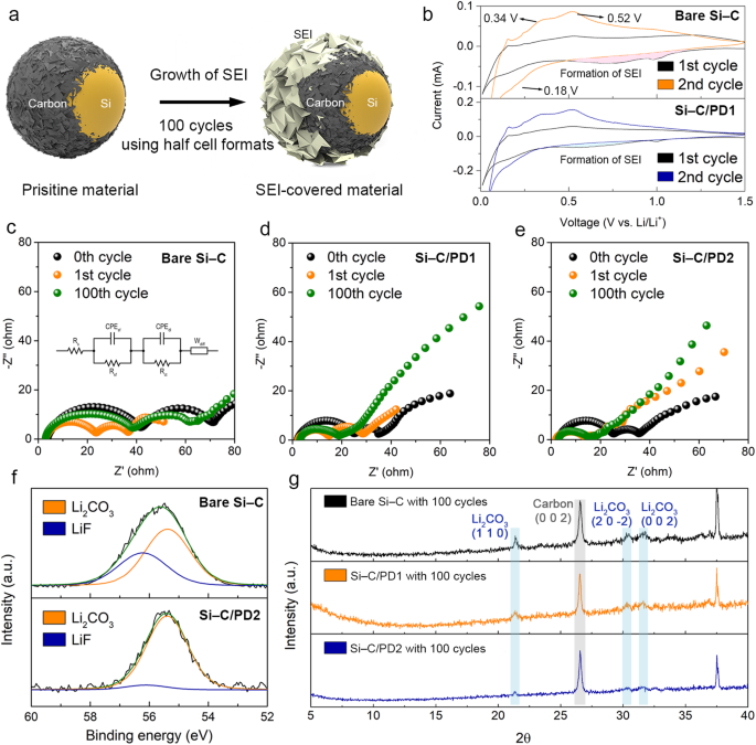
a Schematic depicting the formation of the SEI layer after biking. b Cyclic voltammetry curves of the naked Si–C and Si–C/PD1 samples after the first (black line) and 2nd cycles (orange and blue traces for the naked Si–C and Si–C/PD1, respectively). Nyquist plots of the c naked Si–C, d Si–C/PD1, and e Si–C/PD2 samples after 0 (black circles), 1 (orange circles), and 100 cycles (inexperienced circles). f Li 1s core–stage area of the XPS spectra of the naked Si–C and Si–C/PD2 electrodes after 100 cycles of cell operation, the place blue and orange traces are assigned to LiF and Li2CO3, respectively. g XRD patterns of the naked Si–C (black line), Si–C/PD1 (orange line), and Si–C/PD2 pattern (blue line) after 100 cycles of cell operation.
Moreover, the development of SEI movie development over biking was tracked by assessing modifications in cell impedance by means of EIS analyses (Figs. 5c–5e and Supplementary Desk 5). To look at the evolution of the SEI movie throughout biking, impedance measurements obtained after the first and a centesimal cycles have been in contrast. Particularly, the primary semicircle within the Nyquist plots was thought of, as it’s associated to the resistance of the lively materials floor. The preliminary impedance of the primary semicircle for the naked Si–C composite doubled after 100 cycles. This enhance means that after 100 cycles of cell operation, the floor of the naked pattern was extensively lined with SEI layers, probably impeding {the electrical} conduction of the lively supplies. In distinction, the impedances of the Si–C/PD1 and Si–C/PD2 samples solely skilled a slight enhance even after 100 cycles of cell operation, indicating the minimal development of the SEI layer because of the suppression of the electrolyte decomposition by the PD-based blocking layer. In flip, the inhibition of SEI layer development doubtless contributed to the improved electrolytic efficiencies of the Si–C/PD samples, in the end delaying their capacitive plunging cycles.
To quantify the expansion of the SEI layer, direct XPS and XRD measurements have been performed utilizing the spent electrodes after 100 cycles of operation. These analyses allowed for an examination of the inner chemical and crystallographic compositions of the disintegrated cells. Within the XPS spectra of all of the samples, peaks at 55.4 and 56.3 eV have been noticed, which could be attributed to Li2CO3 and LiF, respectively (Fig. 5f). These Li-based compounds are the first constituents of the SEI layers. Nevertheless, the height comparable to LiF within the XPS spectrum of the Si–C/PD2 pattern was much less distinguished and weaker in comparison with the spectra of the naked Si–C and Si–C/PD1 composites. This remark suggests a discount within the decomposition of fluoroethylene carbonate inside the electrolyte and, consequently, the suppressed formation of LiF within the Si–C/PD2 pattern (Supplementary Fig. 24).
As well as, the quantities of the Li2CO3 and LiF phases have been decided by means of XRD evaluation (Fig. 5g). Notably, no peak comparable to Si was detected within the XRD patterns of all of the samples, primarily because of the prevalent amorphization of Si throughout cell biking. The height at 2θ = 26.5° could be attributed to the carbon-based supplies current within the electrodes, which embrace tender carbon and conductive components. Then again, the height at 2θ = 37.5° could be assigned to the Al-based pattern holder used within the XRD measurements (Supplementary Fig. 25). Extra peaks that may be attributed to the formation of the SEI movies within the electrodes after the biking have been noticed, which have been absent within the patterns of the unused electrodes (Supplementary Fig. 26). Particularly, the peaks at 2θ = 21.4°, 30.3°, and 31.6° corresponded to the (110), (20(bar{2})), and (002) planes of the crystalline Li2CO3 part, respectively. The peaks indicative of the Li2CO3 part within the XRD sample of the naked Si–C composite have been sharper and extra intense in comparison with these within the patterns of the PD-coated samples. This means that extra Li2CO3 was generated on the naked pattern after biking, presumably because of the poorly managed development of the SEI layer. Subsequently, the XPS and XRD outcomes align with the EIS measurements, revealing that the introduction of the PD blocking layer successfully suppressed the electrolyte decomposition.
Moreover, majority of the O and F indicators noticed within the EDS elemental maps of cross-sectional photos, which signifies the presence of SEI layers, have been considerably lowered in PD coated samples (Supplementary Fig. 27). Moreover, the d-spacings of the crystallites obtained by means of chosen space diffraction correlates nicely with these of the (201) and (40(bar{2})) planes of Li2CO3 (Supplementary Fig. 28). Subsequently, the area with robust O and F indicators was recognized because the grown SEI part. Total, the proposed parts and variables for the ELET method can efficiently describe the extent of electrolytic decomposition, as confirmed by the outcomes of the crystallographic, chemical, and imaging analyses.


